Here is a schematic for a low cost, minimal parts count, xenon flash strobe. It uses parts which can be taken from easily obtainable, discarded items so not only is the parts count low, the cost is low. The most distinctive novelty of this circuit is the use of a piezo-electric igniter, rather than a transformer coil, to trigger the strobe. This method has been shown to be extremely reliable for a wide range of flash tubes.
The design is unique in a number of ways. First, it contains no active components – transistors, SCRs, TRIACs, etc. This lowers the cost and complexity compared with most other designs. Second, it contains no transformers for step up DC-DC conversion or flash triggering. This also reduces complexity and cost. Note that there are no resistors required by the design.
There are many, many sites on the internet which explain how to obtain and disassemble disposable flash cameras to remove the flash unit. Both the xenon flash tube and the discharge capacitor are used by this design. It iseasy to obtain used disposable cameras free, with a little charm or ingenuity.
The igniter is a piezo-electric spark generator which can be scrounged from a used or worn-out electronic lighter or BBQ igniter. At least one wire will be attached to the spark unit and the bottom metal cap is the other electrode. Even if you can’t find a discarded unit, you may be able to find a cheap new one at a dollar store. You may also want to improvise a holding fixture for the spark unit to make it easy to use.
The AC line cord can be cut from a discarded appliance, unused AC power adapter, etc. Since the current will be low, any line cord will serve.
To operate the circuit, plug in the line cord, press the charge button for about 10 seconds, then release the charge button. Press the igniter button to fire the strobe.
CAUTIONS and CAVEATS
This is a line operated device. Exposure to lethal voltage is possible unless adequate precautions are taken. Although any line cord would be suitable for the device, as stated above, it is strongly recommended that you find a polarized line cord and connect it with the ground side at the lower pin of the AC plug as shown on the schematic. This assures that the hot side is only accessible at the entry pin for the push button, except during charging. The rectifiers are configured to form a voltage doubler.
The capacitor, C1, must be non-polarized. This requirement is not clear in the schematics for other line operated strobes shown on the internet. The reason is that for a significant number of charging cycles the capacitor may be reverse biased by a considerable voltage. Such a situation can be dangerous for polarized capacitors. There are two reasons for the low value of capacitance for C1. One is that small non-polarized capacitors are cheaper. Low capacitance here has the added benefit that it raises the impedance to the power source so that limiting resistors are not required. The penalty paid is that the charge time for C2 is fairly long – 8 to 10 seconds using the 1 μf value. Do not exceed the 10 μf value for C1 or else a limiting resistor will be required. Also observe that the maximum voltage across C1 is only the line voltage. The action of the doubler circuit is such that C1 is charged to the line voltage and then added to the line voltage on a subsequent half-cycle to create 2x120V on C2.
Note that when a capacitor discharges through a xenon flash tube, it does not discharge to 0 volts. It only discharges down to the extinguishing voltage of the flash tube. This voltage may be on the order of 50 volts, so be warned that the capacitor may still carry some charge long after the strobe has fired.
Finally, C2, if taken from a flash camera, is usually rated at 330 VDC. The actual voltage available from the doubler which drives the charging circuit>may exceed this slightly. Most electrolytics will tolerate small overvoltage without problems, but forewarned is forearmed.
A pdf version of this circuit and writeup can be found here.
The storage capacitors in flash cameras often carry a significant charge long after the camera has been put away. This exposes the hobbyist to a shock hazard during disassembly of the unit. The traditional method of discharging the capacitor, by shorting the leads, causes arcing and can leave burns on the capacitor leads.
Here is a simple setup which can be used to safely discharge the capacitor with minimal shock risk to the user and no damage to any components.
The lamp is a 15W incandescent screwed into an ordinary porcelain base with zip cord attaching it to the adapter. The adapter is made from a Pink Pearl eraser as described in the document here. To use the device, simply place the tip of the adapter between the capacitor leads. The lamp may briefly flash if the capacitor was charged. In any case, the capacitor will now be completely discharged.
A short paper which includes a derivation of the equations for a horizontal sundial is available at sundial.pdf. Such a sundial is a popular fixture in many backyard gardens, but must be designed for the specific latitude where it is used. One layout, developed as an example in the paper is shown in the figure below.
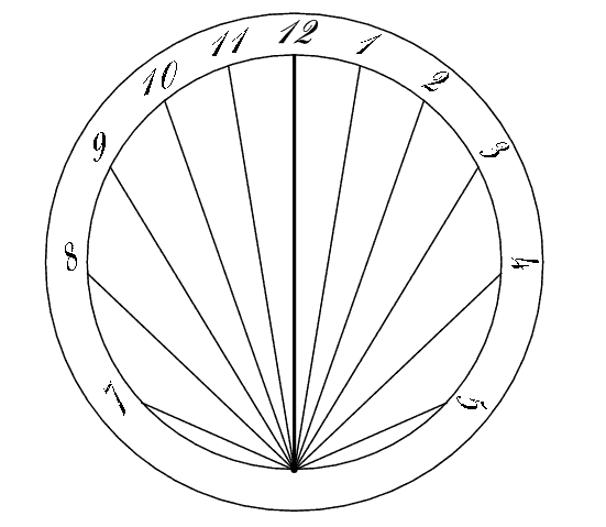
Sundial Layout for 37.4 degrees Latitude
Note that it is possible to design such a sundial for one latitude, but configure it for use at other latitudes by pivoting the noon line (gnomon) vertically up or down the number of degrees required to match the actual latitude. (Up for lower latitudes, and down for higher ones.)
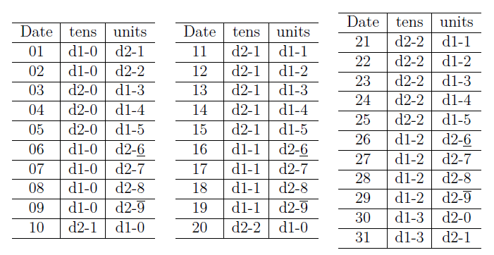
A novelty desk calendar using two dice makes use of a unique property of our Arabic numerals --- namely that decent numeral fonts can be formed with the numerals '6' and '9' being symmetrical inverses of each other. The cubes are held in adjacent positions in a tray or holder and rotated as appropriate to show the current date.
There are only twelve surfaces available, six per cube, so some ingenuity is required to make the full set of 31 numbers available. We first note that the numerals from '0' to '9' do not have to appear on both cubes, since it is only necessary to allow for the numerals from '0' to '3' in the first position (tens digit). All ten digits must be available in the units position, however. For simplicity, we would like to allow the digits '0' to '3' on the first cube, and '0' to '9' on the second, but this requires 14 faces and will not work. It isp> also clear that certain digits must be available on both cubes, since the date '11', and '22' must be represented. A little reflection reveals that the numeral '0' must also appear on both cubes because even though '00' never occurs, because we must allow the numeral '0' to preceded every other numeral -- which would exceed to capacity of a single cube.
We can now devise a trial arrangement with the following assignments:
except that the 2nd cube must have 7 faces. The solution is to use a font which allows us to represent a '9' as an inverted '6'. With this substitution, the problem is solved and a complete day-of-the-month calendar can be provided with two adjacent cubes bearing single numerals on each face. The orientation of each face for each day is shown below: